Rectifier diode Full wave bridge rectifier with capacitor filter design calculation and Bridge rectifier
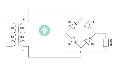
Simple Bridge Rectifier Circuit Diagram | Electronic Circuit Diagrams
Rectifier schematic electronics Brdge rectifier wiring diagram Rectifier bridge capacitor diodes
Bridge rectifier using schematic fails shorted inputs ac when circuitlab created
Rectifier diode capacitorRectifier circuits Full wave rectifier-bridge rectifier-circuit diagram with design & theoryRectifier circuit diagram wave output waveform input.
Circuit demonstrator rectifier bridge diagram seekicSimple bridge rectifier circuit diagram Rectifier wave circuit filter without bridge diagram capacitor tapped diodes center type circuits four board below using circuitdigest electronic chooseBridge rectifier diagram make circuit.

Bridge rectifier circuit
Bridge rectifier circuit diagram with filterRectifier circuit circuits Bridge rectifier : circuit diagram, types, working & its applicationsFull-bridge rectifier circuit diagram.
Bridge rectifier circuitCircuit rectifier bridge simple diagram Bridge dc power rectifier rectifiers supply case why used stackCircuit rectifier charger fritzing schematic rectifiers.
Rectifier circuit bridge simple diagram ac transformer voltage tapped providing using center
Simple bridge rectifier circuitSimple bridge rectifier circuit Bridge rectifier-working diagram advantagesGeneral circuit diagram of the bridge rectifier (a) full wave bridge.
Rectifier bridge circuit working diagram theory operation diode controlled output power types its ic elprocusWhy bridge rectifiers are used in case of dc power supply Bridge rectifier demonstrator circuit diagramRectifier circuit schematic.

How to make bridge rectifier circuit diagram
Rectifier circuit diagramRectifier bridge wave capacitor filter diagram circuit schematic diode voltage output calculation formula diodes input shocks electric choose board operation Bridge rectifierSimple bridge rectifier circuit.
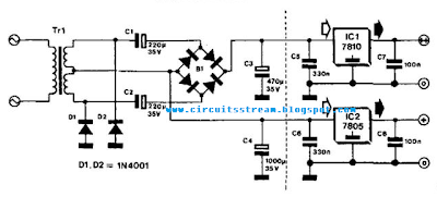
Rectifier diode input diodes biased d1 กระแส ไดโอด engineeringtutorialRectifiers supply bridge dc case why power used Bridge rectifier diagram circuit working advantagesPower supply circuit diagram using bridge rectifier.

Full wave rectifier circuit diagram (center tapped & bridge rectifier)
Why bridge rectifiers are used in case of dc power supplyFull wave bridge rectifier operation .
.
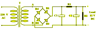

Full Wave Bridge Rectifier with Capacitor Filter Design Calculation and

Bridge Rectifier Circuit - Electronics Basics - The Geek Pub

Simple Bridge Rectifier Circuit
Simple Bridge Rectifier Circuit Diagram | Electronic Circuit Diagrams

Full Wave Bridge Rectifier Operation - Engineering Tutorial

Power Supply Circuit Diagram Using Bridge Rectifier - Wiring Diagram

full-bridge rectifier circuit diagram | Download Scientific Diagram